Aerospace PCB Assembly refers to the specialized process of designing, manufacturing, and assembling printed circuit boards (PCBs) for use in aircraft, satellites, spacecraft, and related defense systems . These assemblies are built to the highest reliability standards because they must function flawlessly in extreme environments where failure is not an option .
Based on the search results, the main types of Aerospace PCB Assembly are categorized by the physical construction of the board and the technology used to assemble them. Each type is chosen for its specific ability to meet the stringent demands of reliability, weight savings, and performance in harsh environments .
Here are the main types of Aerospace PCB assemblies explained in detail.
This is the most common way to classify aerospace PCBs, as the board's construction dictates its application and performance under stress.
| Type | Description | Primary Aerospace Application | Why Use It? |
|---|---|---|---|
| Rigid PCBs | The most common type, built on a solid, inflexible base material (e.g., high-temperature FR4, polyimide) to provide a stable platform for components . | Cockpit instrumentation, auxiliary power units (APUs), control tower systems, and power converters . | Provides the necessary mechanical stability for reliable performance in less space-constrained environments . |
| Flexible PCBs (Flex) | Built on bendable materials like polyimide, allowing them to be twisted, folded, and shaped to fit into tight or irregular spaces . | Interconnecting embedded electronic packages, displays, and backplanes; also used between articulating components like those in satellite solar arrays and sensors . | Reduces system complexity, weight, and assembly time compared to conventional wiring. Their low mass also makes them less susceptible to impact and vibration damage . |
| Rigid-Flex PCBs | A hybrid construction that combines rigid sections (for mounting components) with flexible circuit layers that connect them, essentially creating a 3D circuit structure . | Avionics Line Replaceable Units (LRUs), complex electronic systems where space is at a premium and high reliability is critical . | Eliminates the need for connectors and wiring harnesses between rigid boards, significantly improving reliability and saving space and weight . |
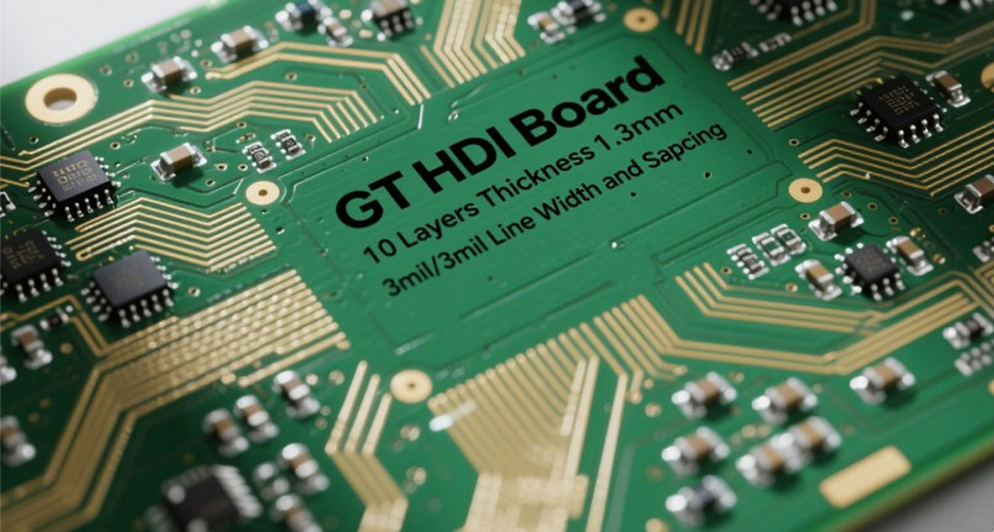
| High-Density Interconnect (HDI) PCBs | These boards feature finer lines, smaller vias, and higher component density, packing more functionality into a smaller footprint . | Emergency response devices, advanced communication systems, and other applications where quick signal transmission and minimal signal loss are essential . | Enables device miniaturization and weight reduction, which are critical for modern aerospace and defense applications . |
| RF/Microwave PCBs | Designed with specialized materials (like ceramic-loaded PTFE) to maintain signal integrity at high frequencies . | Radio communication circuits, radar systems, and other high-frequency applications found in aircraft, satellites, and missiles . | Ensures consistent performance and minimal signal loss in circuits that handle high-frequency radio signals . |
| Metal Core PCBs (MCPCBs) | Use a metal base (typically aluminum or copper) to provide superior heat dissipation . | High-power LED lighting systems, power converters, and other applications where components generate significant heat . | Directly addresses thermal management challenges, pulling heat away from critical components to ensure longevity and reliable operation . |
Beyond the physical board type, the method of attaching components also defines the assembly.
| Assembly Method | Description | Primary Application in Aerospace |
|---|---|---|
| Surface Mount Technology (SMT) | Components are placed directly onto pads on the board surface and soldered. This allows for high-density, automated assembly of complex circuits . | Used for the majority of components on modern, compact avionics and control systems where space is limited . |
| Through-Hole Technology (THT) | Component leads are inserted into drilled holes and soldered on the opposite side. This creates a much stronger mechanical bond than SMT . | Preferred for large, heavy components like transformers, high-capacity capacitors, and connectors, especially in high-vibration environments . |
| Mixed Technology | A single board combines both SMT and THT, using SMT for small, complex parts and THT for components that need extra mechanical strength . | This is the most common approach for complex aerospace assemblies, offering a balance of high-density circuitry and robust physical connections . |
Unlike commercial electronics, aerospace systems operate under extreme conditions and cannot be easily repaired or replaced . The stakes are incredibly high, which is why these assemblies must meet the most stringent requirements in the electronics industry .
Several critical factors drive these rigorous standards : Harsh Operating Environments: Aerospace electronics must withstand extreme temperature fluctuations, high levels of vibration, severe pressure changes, radiation exposure, and potential contact with corrosive elements like salt spray or fuel .
Human Safety: These systems often control aircraft or spacecraft carrying people. A failure can have catastrophic consequences, making safety the absolute top priority .
Extremely High Cost of Failure: A malfunction can lead to the loss of multi-million dollar equipment or an entire mission, resulting in immense financial losses .
Extended Lifespan: Aerospace systems are designed to operate for decades, often without the possibility of maintenance or repair once deployed (e.g., a satellite in orbit) .
Strict Regulatory Compliance: The industry is governed by a strict framework of certifications and standards (like AS9100D, IPC Class 3) to ensure absolute safety and reliability .
System Complexity: Modern aerospace vehicles are incredibly complex, with numerous interconnected electronic systems. The failure of a single PCBA can disrupt the entire operation
To meet these demands, the assembly process involves several specialized characteristics:
Materials must be chosen for performance, not just cost. High-frequency laminates like the Rogers RO4000 series and high-temperature materials like FR408 are common . Components are military-spec (MIL-spec) and must meet very specific tolerances, such as precise metal mixtures in alloys .
These assemblies are built to IPC Class 3 or Class 3A standards, the highest reliability classifications for electronics that require "high performance or on-demand performance" where equipment downtime cannot be tolerated . Manufacturing facilities must be certified to AS9100D, the aerospace-specific quality management standard .
The assembly itself uses high-precision techniques: Nitrogen Reflow Soldering: Using an inert nitrogen atmosphere during soldering prevents oxidation of solder joints, which is critical for long-term reliability . Rigorous Inspection: This goes far beyond standard checks, utilizing 3D Automated Optical Inspection (AOI) for surface defects and X-ray inspection to verify hidden solder joints (e.g., under Ball Grid Arrays) for voids or cracks . Conformal Coating: A protective chemical layer (like acrylic or urethane) is applied to the assembled board to shield it from moisture, chemicals, dust, and extreme temperatures .
Finished assemblies undergo a battery of tests to simulate the rigors of flight and space : Thermal Cycling/Shock: Boards are rapidly heated and cooled (e.g., at 288°C for 10 seconds) to ensure they can survive temperature swings without failing . Vibration Testing: Simulates the intense shaking during launch or turbulent flight to check for mechanical weaknesses . Radiation Hardness: For space applications, components must be resistant to ionizing radiation that can disrupt electronics .
To handle complexity and harshness, aerospace often uses a mix of Surface Mount Technology (SMT) for high-density circuits and Through-Hole Technology (THT) for components that need extra strong mechanical bonds in high-vibration environments . Rigid-flex PCBs are also common due to their light weight, small size, and ability to fit into compact spaces While the applications differ, the underlying approach to manufacturing is consistent. In every case above, the PCB assembly must be "mission-critical." This means they are all built using: Strict Certifications: Facilities are certified to AS9100D, the international quality management standard for aerospace . They also build to stringent military and space standards like MIL-PRF-31032, IPC-6012 Space Addendum, and MIL-STD-883 . Advanced Materials: You'll find specialized materials like high-temperature polyimide, low-loss RF laminates (e.g., Rogers), and even Kevlar in these boards, not standard FR-4 . Rigorous Testing: Assemblies are subjected to extreme thermal cycling, vibration/shock tests (simulating launch or turbulent flight), and outgassing tests (for space) to ensure they won't fail in their intended environment . Protective Measures: Techniques like conformal coating, encapsulation, and potting are used to shield sensitive electronics from moisture, chemicals, and physical stress . In essence, the applications of aerospace PCB assemblies are as vast as the aerospace industry itself, united by the unwavering demand for performance when failure is not an option.
Aerospace PCB assemblies are found in virtually every electronic system on an aircraft or spacecraft : Flight Control Systems: Including "Fly-by-Wire" technology that replaces mechanical controls with electronic interfaces .
Communication & Navigation Systems: Radios (VHF/UHF), radar systems for weather and terrain mapping, and GPS navigation modules . Power Distribution Units: Managing and converting electrical power throughout the vehicle .
Data Acquisition & Processing: Including the "black box" flight recorders that store critical flight data .
Onboard Instrumentation & Sensors: Such as air data sensors (e.g., Pitot tubes) that measure altitude and airspeed.
The specific role of a PCB assembly varies greatly depending on whether it's installed in a satellite orbiting Earth, the cockpit of a fighter jet, or a ground-based radar station.
| Application Category | Specific Functions & Systems | PCB Types & Key Requirements | Real-World Examples |
|---|---|---|---|
| 🚀 Spacecraft & Satellites | Communication Systems: Satellite transceivers, high-frequency radar, and antenna control electronics . Data Handling: Onboard mission computers, data acquisition, and processing units . Power Systems: Solar panel power controllers, power conditioning units (PCUs), and battery management systems (BMS) . Guidance & Control: Attitude control systems and navigational units . | High-Frequency/RF PCBs: Built with specialized laminates (e.g., PTFE) for signal integrity at mmWave frequencies . Rigid-Flex & HDI PCBs: For weight and space savings in compact satellite payloads . Heavy Copper PCBs: For power distribution and thermal management . | ISRO's INSAT, GSAT, and RISAT satellite series, which utilize precision-engineered subsystems and components . |
| 🚁 Launch Vehicles (Rockets) & Shuttles | Guidance & Navigation: Flight control computers and inertial guidance systems that steer the vehicle . Propulsion Control: Rocket engine control electronics and thrust vector control modules, which direct engine thrust . | Rigid PCBs: For stable, high-reliability performance under extreme vibration. High-Temperature Materials: Polyimide laminates to withstand the thermal stress of launch and atmospheric friction . | Flight control systems in vehicles like the now-retired Space Shuttle or modern commercial launchers. |
| ✈️ Aircraft (Civil & Military) | Flight Control Systems: "Fly-by-Wire" systems that translate pilot inputs to electronic signals for control surfaces . Navigation & Communication: GPS, VHF radios, and transponders . Power Distribution: Managing and converting electrical power throughout the aircraft . Monitoring & Instrumentation: Onboard sensors for air data, engine health, and cockpit displays . | Mixed Technology (SMT & THT): Combines high-density circuitry with robust through-hole connectors for vibration resistance . Flex & Rigid-Flex: Used in wing folding mechanisms, cockpit instrument panels, and other space-constrained areas . | Systems onboard military aircraft like the C-130 Hercules, CH-47 Chinook, and commercial jets like the Boeing 757 and 767 . |
| 🛡️ Defense & Ground Systems | Radar Systems: Ground-based and ship-based radar for surveillance and targeting . Secure Communication: Encrypted data links and tactical communication terminals . Weapons Systems: Control electronics for missiles and smart munitions . | RF/Microwave PCBs: For high-frequency radar signals. MIL-Spec Assemblies: Built to withstand harsh field conditions, shock, and temperature extremes, often with conformal coating for environmental protection . | Mobile Satellite Service (MSS) terminals and Automated Weather Stations used in remote defense operations . |
| 🛸 Exploration Vehicles | Rovers & Landers: Control and processing units for mobility, robotic arms, and scientific instruments (e.g., sample analysis) . Deep Space Probes: Systems for long-range communication and data collection in deep space. | Radiation-Hardened PCBs: Materials and designs that can withstand high levels of cosmic radiation. High-Reliability Interconnects: Plated through-holes and vias designed to endure extreme thermal cycling without cracking . | The flight computers and instrument controllers on rovers like NASA's Perseverance or Curiosity . |
| 🛸 Uncrewed Aerial Vehicles (UAVs) / Drones | Flight Controllers: The "brain" that processes sensor data and controls motors . Payload Control: Systems for cameras, sensors, and data links. | High-Density SMT PCBs: To pack powerful processors (like ESP32-S3), sensors, and communication modules into a tiny, lightweight frame . Double-Sided Assembly: Maximizes space on miniaturized boards . | The flight controller board inside a compact, high-performa |
Aerospace PCB Assembly refers to the specialized process of designing, manufacturing, and assembling printed circuit boards (PCBs) for use in aircraft, satellites, spacecraft, and related defense systems . These assemblies are built to the highest reliability standards because they must function flawlessly in extreme environments where failure is not an option .
Based on the search results, the main types of Aerospace PCB Assembly are categorized by the physical construction of the board and the technology used to assemble them. Each type is chosen for its specific ability to meet the stringent demands of reliability, weight savings, and performance in harsh environments .
Here are the main types of Aerospace PCB assemblies explained in detail.
Getting the best Aerospace PCB Assembly solutions requires a meticulously structured approach that prioritizes absolute reliability, stringent compliance, and zero-defect manufacturing above all else. Unlike commercial electronics, these assemblies must function flawlessly in extreme environments where failure is not an option and repairs are often impossible .
Here is a comprehensive guide to securing a partner and process that can deliver mission-critical performance.
In aerospace, a supplier's certifications are not just paperwork; they are the primary evidence of their capability. You must verify these directly .
AS9100D: This is the cornerstone international quality management standard for the aerospace industry. It goes beyond ISO 9001, adding stringent requirements for product safety, risk management, counterfeit parts prevention, and traceability . Your partner must be AS9100D certified.
IPC Class 3 / Class 3A: This is the highest reliability classification for electronics. It sets strict acceptance criteria for PCBs intended for high-performance applications where downtime cannot be tolerated .
Additional Critical Standards: Depending on the specific application, your partner must be adept at building to other key standards. A good partner will be familiar with all of these.
| Standard | Focus Area |
|---|---|
| IPC-6012DS | Enhanced qualification and performance requirements for rigid PCBs in aerospace/military applications . |
| MIL-PRF-31032 | Ensures the military performance of PCBs . |
| NASA-STD-8739.1/8739.4 | Workmanship standards for soldered electrical connections, critical for spaceflight hardware . |
| MIL-STD-883 | Test method standard for microcircuits, essential for high-reliability assemblies . |
| J-STD-001 Space Addendum | Additional requirements for soldering in space applications . |
Aerospace PCBs often involve complex technologies that standard assemblers cannot handle. You need to ensure your partner has proven expertise in these areas.
Advanced Board Technologies: Look for a partner experienced with High-Density Interconnect (HDI) , rigid-flex, flexible PCBs, and high-frequency/RF materials like Rogers laminates. These are essential for meeting the size, weight, and signal integrity demands of modern aerospace systems .
Precision Assembly: The best partners achieve component placement accuracy down to ±25μm or better . They should be proficient in both Surface Mount Technology (SMT) for high-density circuits and Through-Hole Technology (THT) for components that require superior mechanical strength in high-vibration environments .
Hybrid and Microelectronics Assembly: For the most demanding applications, you may need a partner capable of hybrid microelectronics assembly. This can include processes like epoxy die attachment, wire bonding, and working with bare dies, requiring precision and experience to ensure repeatable yields .
Design for Manufacturing (DFM) Partnership: The best solutions begin before a single component is placed. Your partner should offer a collaborative DFM review, providing feedback on your design to optimize it for manufacturability, reliability, and testability. This includes considerations like material selection, stack-up, thermal management, and even allowing for board outgassing in space applications .
Given the cost of failure, testing is not just a step in the process; it is the process. A multi-layered strategy is non-negotiable.
In-Process Inspection: This begins with Automated Optical Inspection (AOI) to catch surface-level defects. X-ray inspection is critical for verifying hidden solder joints, such as those under Ball Grid Arrays (BGAs), checking for voids or cracks .
Environmental Stress Testing (EST): Your assemblies must be proven to survive their intended environment. This includes thermal cycling (e.g., -55°C to +125°C), vibration testing (simulating launch or flight), and humidity testing .
Functional Testing: The final assembly should be tested under power to verify it performs its intended function. The best partners conduct full functional tests over temperature to ensure performance across the entire operating range .
Protective Measures: To ensure longevity, assemblies should be protected with conformal coating (acrylic, urethane, silicone) to shield against moisture, chemicals, and contaminants. For extreme conditions, encapsulation or potting may be required .
Selecting the right partner requires going far beyond a website or a quote. You need to verify their capabilities and stability firsthand.
Verify Certifications and Data: Don't just look at a logo on their site. Request certificates and, if possible, verify them directly with the issuing body . Ask for data on their first-pass yield, defect per million opportunities (DPMO) , and on-time delivery rate (aim for ≥95%) .
Perform Facility Audits: Whenever possible, visit the factory in person. If that's not feasible, request a detailed virtual tour. Walk the production floor, inspect the quality lab, check their ESD control measures, and meet the engineers and operators . Ask probing questions about how they handle rework, manage tooling calibration, and control processes .
Assess Financial and Operational Stability: Can they survive an economic downturn and scale with your needs? Inquire about their financial health and ask for audited financials if possible. Understand their contingency plans for supply chain disruptions, natural disasters, or geopolitical issues .
Validate with a Pilot Project: Before committing to a large production run, start with a prototype or small pilot batch. This is the ultimate test. Use it to evaluate their communication, the accuracy of their DFM feedback, the quality of their work, and their ability to meet deadlines . Test the prototype rigorously in your own environment.

 Hindi
Hindi
 Chinese
 Japanese